The Holodeck - Part I
Getting Started
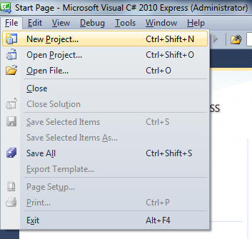
To get started open up Visual Studio 2010 and go to the File menu, select New Project.
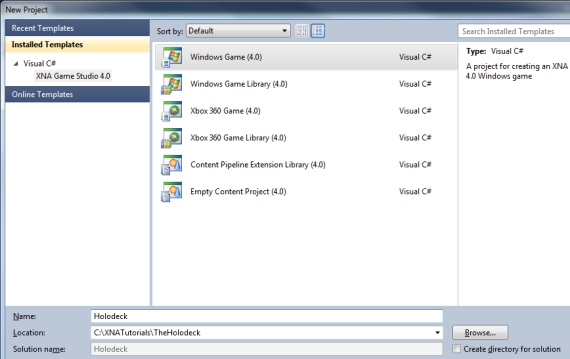
Next, you'll want to select "Windows Game (4.0)". Then name your project Holodeck and you can set the location if you like.
I like to start by renaming my game1.cs file to something specific for the project I’m working on.
Click on the tab for the Game1.cs code to select it, and then click on the File menu and choose the “Save As” option. If you don’t click on Game1.cs first, your “Save As” option will try and save the Project instead.
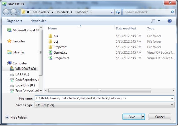
This will change your namespace in both this .cs file as well as Program.cs, as well as the file name.
The change to namespace is shown below:
using System;
using System.Collections.Generic;
using System.Linq;
using Microsoft.Xna.Framework;
using Microsoft.Xna.Framework.Audio;
using Microsoft.Xna.Framework.Content;
using Microsoft.Xna.Framework.GamerServices;
using Microsoft.Xna.Framework.Graphics;
using Microsoft.Xna.Framework.Input;
using Microsoft.Xna.Framework.Media;

namespace Holodeck
{
    /// <summary>
Creating Art Work for our Program
Now that we've got our project setup in Visual Studio 2010, let's take a step back. We need some way to create our holodeck "room". Theoretically, you could do that all by writing computer code. The biggest problem you would have would be creating an image for the "wall paper". Punching in numbers for every dot drawn on the screen would be ridiculous and you would never get anything done because of all the time it would take. You'll see a little of that when we create the .x file.
With the "wall paper" we're going to create it in some sort of picture drawing program and then import it into the game. Before we do that though, we need a "room" to have a place to put our "wall paper".
The Holo-Deck Room Model
Next we want to start building the holo-deck. This is just going to be a very simple room. We’re going to create the model for the room using a .X file, which is the standard file type for models in DirectX and XNA.
I used DirectX Viewer that comes with the DirectX SDK to view this model as I was working on it. You could download the DirectX SDK, but I wouldn’t recommend it unless you have a specific reason to do that. DirectX Viewer is not a very good program for viewing models. I just used it because it gets the job done and can read .X files. And I already had the DirectX SDK installed from working on C++ DirectX programs.
If you can’t find a program out there that reads .X files, you can make one yourself using XNA. Actually, that’s pretty much what we’re doing now; so it won’t help you until you’re done. But I’ve got all the code here and ready to go. So, you shouldn’t have any problems.
If you don’t know what a Vertex, Edge, or Face is take a look at this website for an explanation:
http://www.mathsisfun.com/geometry/vertices-faces-edges.html
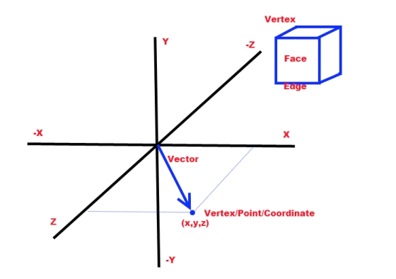
And above is my drawing to kind of show you what an edge, face, and vertex is. It's just that the other site does a better job of explaining it. We're going to be defining the vertices, edges, and faces of our cube/room/holodeck in the .X file.
Go into Notepad and paste the text for this file. (If you don’t know, you can usually go to the Start Menu and Run or the Start Search box and just type in Notepad. Or you can probably find it under Accessories.) Be sure and change the file extension from .txt to .x when you save the file and you should name it HoloDeckMesh.x in order for it to work with the rest of the tutorial.
One of the reasons I chose the holodeck as a place for our virtual reality is because it's basically a cube shaped room. We could build the room by defining vertices and indices and drawing the room using code, but there is a much easier way. We're going to use a model.
A model is an object that we will put into our 3D environment. Basically every 3D object is a model. Usually, what you do is use a modeling program to digitally sculpt the object. Then you save the model to a .X or .FBX formatted file. And once you have that file you can use the file to import the model into XNA and finally into the scene you are drawing. We're going to ignore the .FBX files for now and focus on .X files. They are both very similar although it seems to be easier to get models animated with .FBX files. We'll come back to those later.
The .X file format is a file format designed for DirectX. DirectX is Microsoft's API/interface allowing programmers to write Windows programs that communicate directly with the graphics card. Without something like DirectX graphics programs would run too slow for anyone to run them in Windows. Before DirectX, game programmers wrote their games to run in DOS in order to avoid running them in Windows. XNA uses DirectX under the hood. So, it kind of made sense that Microsoft would make .X the "official" model file for XNA.
Normally, you would use a modeling program like Maya or 3D Studio Max in order to create a .X file or other file for your model. We'll be using Google's Sketchup and Blender to create our model files (later) because both pieces of software can be downloaded for free. Pretty much no modeling program supports .X files "straight out of the box". You pretty much always have to install some add-on to get the program to work with .X files. Blender actually just has a preferences menu option where you can turn .X file exports on. I think you can do that without any additional download. Unfortunately, there doesn't seem to be an importer for .X files in Blender, even as an add-on. Most other programs are going to require you to find a .X add-on and install it in order to save the model as a .X file.
However, for the holodeck we are going to be making a .X file by hand. Or rather, I made it by hand and you'll probably copy and paste it. But it'll still be a mostly manual process creating it and I didn't use anything except Windows Notepad and a keyboard to create our "room" for the holodeck.
Since the room of the holodeck is nothing more than a simple cube, it's just about the easiest model you can possibly create by hand. Once you see the difficulty of creating such a simple object, you'll quickly grow to appreciate why you need a modeling program to create your average game object which may literally be a million times more complex than a cube. But by creating this simple model by hand, you will get an understanding of what a .X or .FXB file actually is. All the modeling programs will be doing for us is creating these files. Nothing else.
So, open up Windows Notepad. You'll probably find it under the Accessories folder. You can use any text editor program for this, but I use Notepad because it's so basic. If you use Microsoft Word, for example, it's probably going to put a lot of formatting and garbage in the file that will cause the file not to work. You want nothing in this file other than exactly what we put in. Notepad's perfect for that job. You will just have to remember that Notepad likes to save files with a .Txt extension and our file will need a .X extension to work right.
Here's the text for the .X file. You are welcome to copy and paste it into your Notepad file:
xof 0302txt 0064     //Required to be all on one line with this exact spacing.
//xof MUST be the first thing in the file. It tells the program reading it that it's a .x file.
//0302 is the version #.
//txt is the file type.
//0064 is the number of bits in a float value.
//Some info on the .X file format can be found at the website below
//http://local.wasp.uwa.edu.au/~pbourke/dataformats/directx/#xfilefrm_Template_Mesh

Mesh HoloDeckMesh //Our mesh is named HoloDeckMesh.
{
       24;                  //Number of vertices we are defining
       //You can define the vertices in any order. Each vertex is x,y,z coordinates.
       //You just have to be able to know where each vertex is at when you go to
       // wind them. For that reason I suggest keeping them in order.
       //Notice that I am defining them in winding order to make winding easy.
       -1.0;  1.0; -1.0;,   //Left up     back   //Back face
        1.0;  1.0; -1.0;,   //Right       up     back
        1.0; -1.0; -1.0;,   //Right       down   back
       -1.0; -1.0; -1.0;,   //Left down   back
        1.0;  1.0;  1.0;,   //Right up    front  //Front face
       -1.0;  1.0;  1.0;,   //Left up     front
       -1.0; -1.0;  1.0;,   //Left  down  front
        1.0; -1.0;  1.0;,   //Right down    front
       -1.0;  1.0;  1.0;,   //Left up     front  //Top face
        1.0;  1.0;  1.0;,   //Right       up     front
        1.0;  1.0; -1.0;,   //Right       up     back
       -1.0;  1.0; -1.0;,   //Left up     back
       -1.0; -1.0; -1.0;,   //Left down   back   //Bottom face
        1.0; -1.0; -1.0;,   //Right       down   back
        1.0; -1.0;  1.0;,   //Right       down   front
       -1.0; -1.0;  1.0;,   //Left down   front
        1.0;  1.0; -1.0;,   //Right       up     back   //Right face
        1.0;  1.0;  1.0;,   //Right       up     front
        1.0; -1.0;  1.0;,   //Right       down   front
        1.0; -1.0; -1.0;,   //Right       down   back
       -1.0;  1.0;  1.0;,   //Left up     front  //Left face
       -1.0;  1.0; -1.0;,   //Left up     back
       -1.0; -1.0; -1.0;,   //Left down   back
       -1.0; -1.0;  1.0;;   //Left down   front

       //IndexBuffer
       // When I first saw an example where they were drawing quads instead of triangles
       // I was a bit confused. As I got looking at the .X file standard I realized that
       // the standard says you can use either one. Defining Quads is probably easier to
       // understand when drawing a cube, so we might as well do it with quads.
       6;                   //6 faces
       4; 0, 1, 2, 3;,            //Wind (define) the vertices in clockwise order.
       4; 4, 5, 6, 7;,
       4; 8, 9,10,11;,            //Every line starts out with 4 because these are quads.
       4;12,13,14,15;,
       4;16,17,18,19;,
       4;20,21,22,23;;

       //Paint our Mesh
       MeshMaterialList
       {
              1; 1; 0;;     //One material used for every face starting with face zero
              Material      //Material has no name
              {
                     1.0; 1.0; 1.0; 1.0;; // R = 1.0, G = 1.0, B = 1.0
                     0.0;
                     0.0; 0.0; 0.0;;
                     0.0; 0.0; 0.0;;
                     TextureFilename
                     {
                           "GridTexture.png";   //Change this if you want to use a different texture name.
                     }
              } //end of Material
       } //end of MaterialList

       MeshTextureCoords
       {
              //Here we start doing UV mapping to "paint" the mesh.
              //We're going to "stretch" our texture across the mesh and
              //these coordinates "pin down" the texture at these points.
              //So we're matching up vertices with position in the picture/texture.
              //1.0 would be 100% of the texture. So 10 is 1000%.
              //This says I want to use the texture 10 times across the face.
              //You can experiment with this by changing all the 10.0’s to 1.0
              //and watching what happens.


              24; //24 vertices to map/connect to.
               0.0;  0.0;  //Left  up     back   //Back face
              10.0;  0.0;  //Right up     back
              10.0; 10.0;  //Right down   back
               0.0; 10.0;  //Left  down   back

               0.0;  0.0;   //Right up   front  //Front face
              10.0;  0.0;   //Left up     front
              10.0; 10.0;   //Left  down front
               0.0; 10.0;   //Right down    front

               0.0;  0.0;   //Left up     front  //Top face
              10.0;  0.0;   //Right      up     front
              10.0; 10.0;   //Right      up     back
               0.0; 10.0;   //Left up     back

               0.0;  0.0;   //Left down   back   //Bottom face
              10.0;  0.0;   //Right      down   back
              10.0; 10.0;   //Right      down   front
               0.0; 10.0;   //Left down   front

               0.0;  0.0;   //Right      up     back   //Right face
              10.0;  0.0;   //Right      up     front
              10.0; 10.0;   //Right      down   front
               0.0; 10.0;   //Right      down   back

               0.0;  0.0;   //Left up     front  //Left face
              10.0;  0.0;   //Left up     back
              10.0; 10.0;   //Left down   back
               0.0; 10.0;   //Left down   front
              ;

       }
} //end of Mesh HoloDeckMesh
Believe it or not, we have about 3 pages of code there and all it does is contain the information for "how to draw a box".
I've marked up the text in this file with comments like crazy. Basically, any time XNA sees two forward slashes (//) it will ignore everything after that until it gets to the next line. I've used that to write comments about what's going on in the file. You should find it helpful to read those comments to understand what's happening in the file.
You will notice that it calls our model a "mesh". A mesh and a model are pretty much the same thing. The term mesh comes from the days when models were "wire frame" instead of textured. The models looked like they were made up of wires and so mesh was a fitting name for them. And the name has kind of stuck. Regardless, whether you call it a mesh or a model it's an object that will be placed into our virtual reality.
Basically, the first line of the .X file just tells a program that reads the file what type of file it is.
After that, the file gets down to business and starts defining the vertices that make up the mesh/model. Vertices are just points in 3D space that have an x,y, and z position. If that doesn't make sense to you, you probably want to go read the "How to Make Things Move" tutorial in the Fundamentals section.
So the vertices are just points, or positions, in 3D space. We are going to draw "lines" between these points called Indices in order to define our model. For our box/cube/room/holodeck, the vertices are just going to be the points where the corners of the box are at.
You may notice that our box is pretty small. It's a cube that is 2 units wide. We'll resize it when we bring it into XNA. We just need it to have the correct shape. I'm still debating on whether I should have made it 1 unit wide. It would have made more sense once we got into XNA but it might have made reading the .X file a little more difficult. All those 1.0's and -1.0's would have been 0.5's and -0.5s.
Notice the way the box is being defined, it has it's center right in the middle of the box. How the model is positioned in the file will determine how it's positioned in XNA, when it's brought in. However, you can move it as soon as you get it into XNA. Repositioning is no big deal.
After all the x,y,z positions of the vertices are defined, the file gets down to defining the indices. An index is basically just an "edge" drawn between the two points. Normally, we draw everything in XNA using triangles. The .X file format allows you to draw objects using "quads" instead of triangles, if you like. Quads are two dimensional four sided objects like a rectangle or a square. XNA doesn't recognize quads, but XNA is smart enough to correctly import a model defined using quads. We'll take advantage of that and draw our room/box/cube/holodeck using quads instead of triangles.
The indices are just the order in which XNA will draw edges, or lines, between the vertices.
So, "4; 0, 1, 2, 3;" will tell XNA "this is a four sided object we're drawing (a quad)". "Draw from the 0 vertex to the 1 vertex (Computers prefer to start counting from zero rather than one). Then draw from 1 to 2. And finally define an edge between vertex 2 and vertex 3."
The order that you define these indices in is very important. You want to define them in clockwise order. This is called the "winding order".
By defining the indices in clockwise order, you are telling XNA which side of the object is the "outside" to be drawn and which side is the "inside" to not be drawn. Not drawing the insides of objects is called "Backface Culling" and it makes your program run a whole lot faster. You almost always want to have Backface Culling turned on. But that means the insides may not be drawn which can cause problems if you wind your indices in counter-clockwise order and end up defining the model inside out.
Now for our holodeck cube, we are using the model as a room so we want the cube painted inside out. That's because we are going to be standing inside the room. Normally, you want to be on the outside of objects that you are drawing, but in the case of a room or skybox (we'll talk about skyboxes later) you want the inside painted and the outside culled. So, you wind all the indices backwards from other models. Incidentally, if you can't find a model that "should" be drawn on the screen but isn't, the first thing you want to do is turn off backface culling, but we'll talk about that later.
After the indices, the file has the shape of the box/cube/room/holodeck defined. So, then it has instructions for XNA on how to paint the box/cube/room/holodeck. A material is basically a method of drawing the object. In this case, the material is going to be the "wall paper" that's going on the walls. Actually it will go on the floor, the ceiling and basically all over the room. You'll notice that it says to use "GridTexture.png". That's a picture file that we are going to build here shortly.
After that, UV coordinates are defined for the model. UV coordinates are kind of like XY coordinates, but for picture files. I think they chose UV partially because XY was already taken.
We'll go into UV coordinates here in a minute when we start drawing our picture file.
And that's pretty much the entire .X file. That's basically all there is to it. You can put more stuff in a .X file, but you will see that this simple .X file gets the job done.
You can find more information on the web, if you are interested in learning more about the .X file format.
http://local.wasp.uwa.edu.au/~pbourke/dataformats/directx/#xfilefrm_Template_Mesh
Also, you should know that you may end up reusing this .X room/cube/box/holodeck model in every XNA program that you make from now on. Right now you're probably thinking it's unimportant, but you'll see later that this "box" is actually a core part of almost every 3D program you are likely to create for quite awhile. It's what we call a "skybox", and skyboxes are used in basically all 3D programs. That's a big part of the reason I've taken the time to have you create it by hand and walk you through it's code almost line by line.
UV Mapping
Ok. Now let's look at how a picture file is used to paint a model like our room. Let's start with UV coordinates.
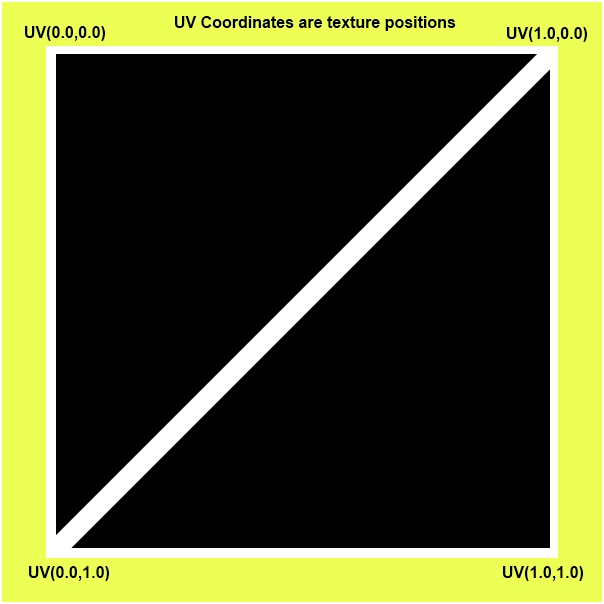
Basically, UV coordinates are just positions in our picture file. U=0,V=0 is the upper left corner in the picture. U=1,V=1 is the bottom right corner of the picture. You can see an example of UV coordinates in the illustration below.
What you are doing with these coordinates is telling XNA how to "stretch the picture across the model/mesh/object. Usually, it's like your model is a grey sculpture that needs to be painted. And with a lot of models it's like you're going to take an actual photograph on a piece of paper and "paint" the sculpted model by gluing down the picture that you stretched over the model. Essentially, you're going to tell XNA "Pin this part of the picture to this point on the model and stretch the picture in between the points I define."
So, in the .X file, you see "0.0; 0.0;". That's saying, "for the first vertex defined, pin the U=0.0,Y=0.0 position to the first vertex." And then it just goes through the vertices of all six faces, in order, and "pins" the picture file positions to the vertices in the model.
You'll notice real quick that the UV coordinates are 10.0 and not 1.0. That's going to tell XNA to repeat the picture 10 times as it stretches the picture across the model between the defined vertices.
The picture that we will be using to "paper" the walls with is shown below:
We are going to "paste' this picture across every wall, ceiling, and floor. We "could" just draw it once on each side of the box. But I want it to form a sort of "grid" pattern across the walls. So, by specifying the UV coordinates as 10.0 instead of 1.0, I'm telling XNA (or any program that reads this model file) that I want it stretched and repeated 10 times across every face of the cube in every direction. So, every face of the cube will have this picture drawn on it a total of 100 times (10 * 10=100).
You can change the number of times the picture repeats by changing 1.0 to the number of times you want it to repeat. UV(7.0,7.0) will stretch from UV(0.0,0.0) seven times. Be aware that you can define UV coordinates as negative and it will flip the picture backwards.
And that's basically all there is to defining our model. You could probably make a pyramid or some other model by writing a .X file, like this by hand. But you can see how many vertices, indices, and UV coordinates have to be defined for an object that has ONLY six flat sides. Most models in actual games have about a million sides these days with UV coordinates that are almost impossible to imagine. Needless to say, this is probably the last time you will ever create a .X file by hand. Although we will reuse this particular file a whole lot.
Once you've got this text in your Notepad file, save it with a .X extension instead of the standard .txt file extension as HoloDeckMesh.x instead of HoloDeckMesh.txt. This file needs to be saved in the Contents folder of your XNA project, but you can save it anywhere for now and move it there when we look at the Contents folder here in awhile. There's an easy trick to finding the Contents folder that I'll show you once we get back into Visual Studio.
Summary
In Part I we're going to review starting an XNA project as we create our new project. Then we're going to build a .X model file by hand, in order to learn how .X files are built as well as needing the file to model our holodeck room. We're also going to define how the model is "painted", or textured, in the .X file and begin discussing how this is done including a discussion on UV mapping.